GPS Dog Tracker/Locator

This is an ongoing project but here’s where i’m at for now. After recently getting a puppy I was looking into what dog trackers are on the market an found all of them to either be Bluetooth based meaning a very short range of about 20 meters. Or GSM mobile carrier based costing a lot and and having to pay a monthly subscription.

I had heard of some new radio transmitters called LORA which in theory could transmit over 1/2 mile. So got hold of 2 and been experimenting if I could build something that would do the job of tracking an object over longer than Bluetooth and no monthly fee.

Firstly the tracker that goes on the dog would need, GPS (obviously other wise I wont know where it is), and the LORA transmitter to send a signal to a receiver and some form of arduino to do the processing. I chose a small nano one. That part was relatively easy to make and the test setup is below.

dog Tracker

The receiver has to do a lot more work. It too needs know where it is, so needs a GPS. It needs the LORA chip to receive a signal from the tracker. It also needs a display to tell me where to head and what’s going on with the device. Lastly it needs a compass to tell me which direction to go. The outcome of that is you need all this on the receiver.
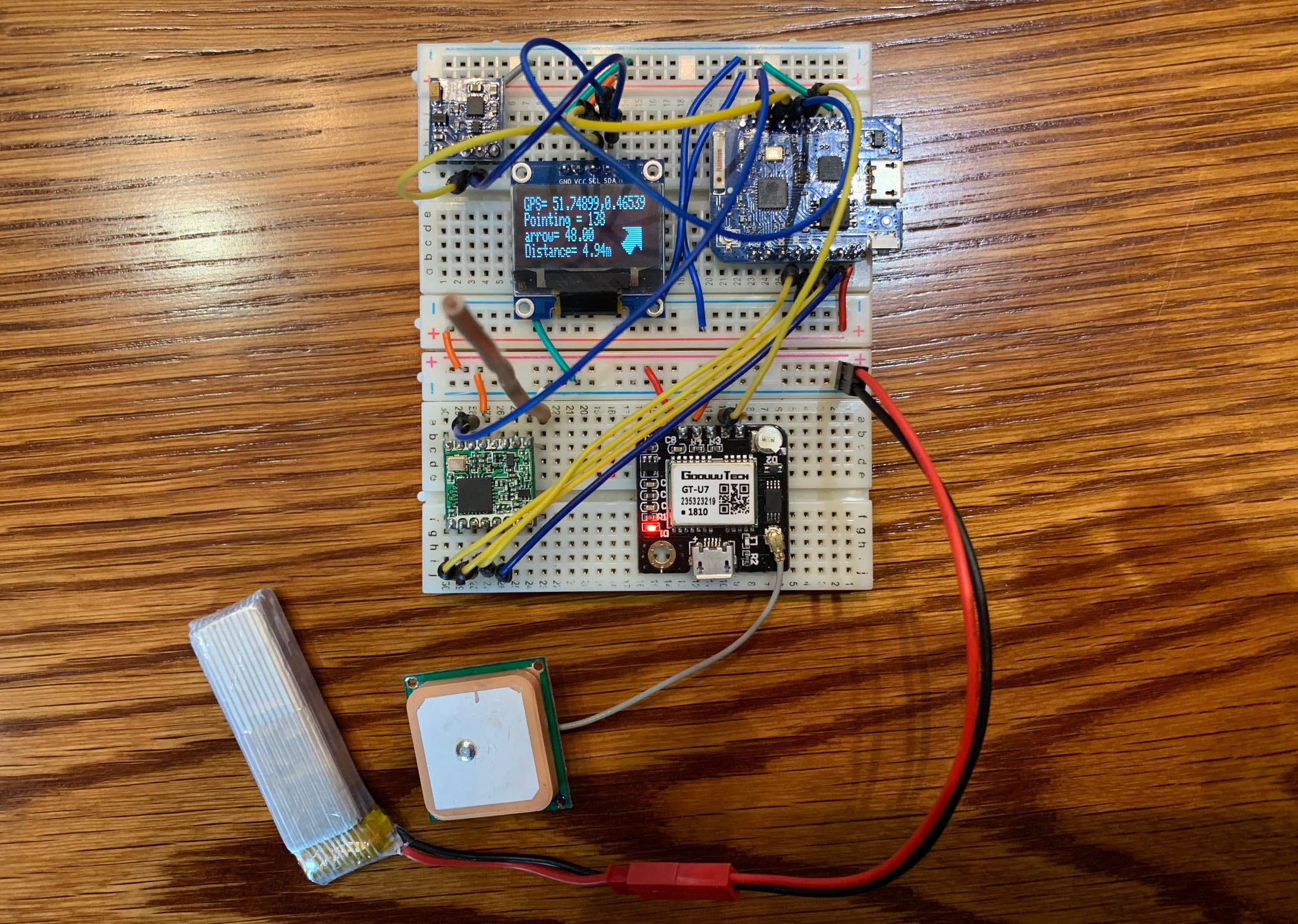
Tracker Receiver

It’s at the stage now for testing it and with a lot of code on the receiver I had to change from an Arduino nano to a ESP8266 wemos device just to fit all the code in the memory. I’ve been running a few tests and to my surprise these little LORA chips are capable of sending a signal at least 200 meters through a pretty built up area. I’m still having a few issues with the compass module (its a cheap China clone model). So waiting on a different compass chip, when that arrives I’ll be able to test it out in an open space to see how far these LORA chips really can go.

Design and Manufacturing PCB

After viewing a number of tutorials about creating a bare bones Arduino Uno I though I’d order the parts and give it a go. After mocking up the arduino using a simple breadboard layout I thought I’d see if it was feasible to turn the breadboard into a fully printed circuit board.

After a bit more research I found a piece of software called Fritzing which can be used to layout a PCB design ready for manufacture. The result of the design I created is below.

PCB Design

It took a bit of time and i went a bit over board from the bard bones arduino adding in voltage regulators so it could be powered from anything from 5v – 9v and also added in voltage regulators so i could get 3v out pins as well. I also decided to create pin outs for all the pins which was a bit overkill.  After finishing the design Fritzing gave me the option to export as a Gerber File. Not something I’d heard of but it basically exports all the layers required for manufacture of the board, ie copper layers, solder layers, silk screen printing ect…

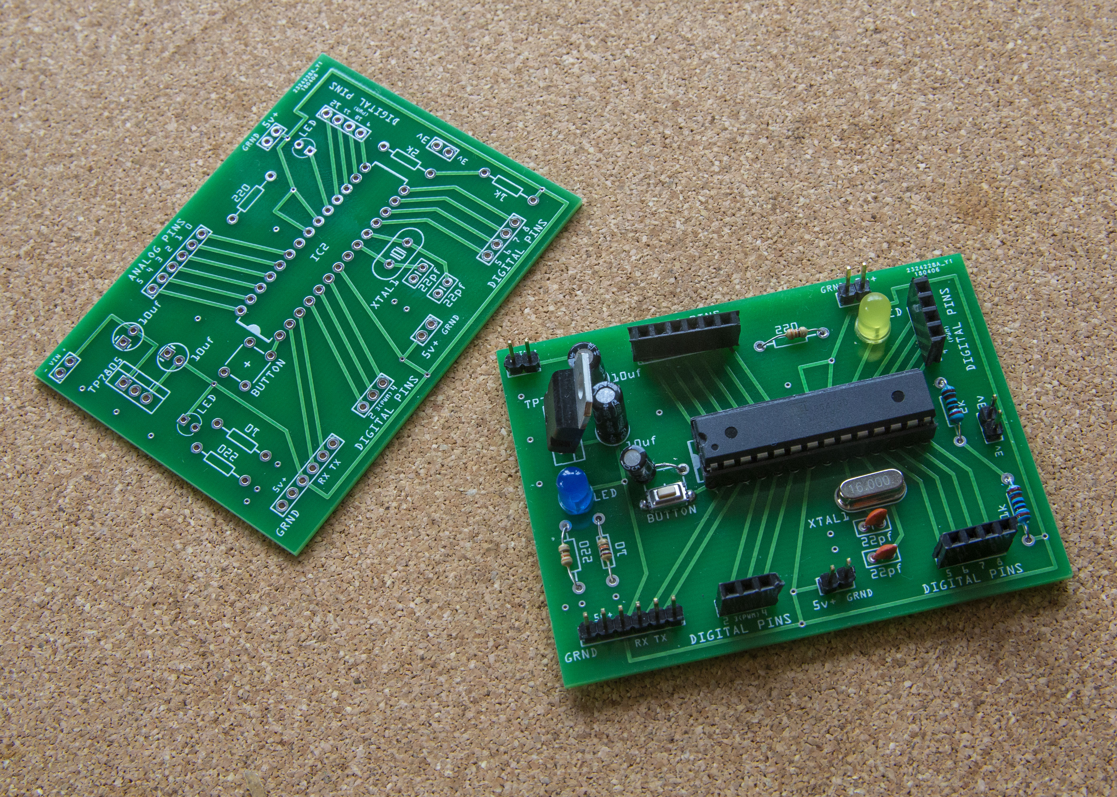
After a bit more research I found a company in China offering amazing deals on PCB manufacturing called JLCPCB. You upload the files and can view exactly what its going to look like. I sent the design off and also created another PCB design at the same time to save on delivery costs. The other PCB I was going to use for mounting different types of Arduinos, and ESP8266 boards. The results back from China were way better than I expected. I also got 10 of each as that was the minimum order.

PCB Boards in Raw

After getting the PCB boards back I mounted all the components onto them and everything worked, almost first time. I had to add an extra capacitor to the board near the reset button which wasn’t on the designs. But not a mistake on my part more a bit of added safety.

PCB Bare Bones Arduino

Finally I sliced and diced the other board I had produced into the smaller mounting boards I am going to use should I need to put something like an ESP01 onto a PCB. Below is a simple board I made in order to easily program the ESP01 as it doesn’t mount into a standard breadboard.

PCB ESP01 programmer


Pond Water Level using NodeJS and Arduino

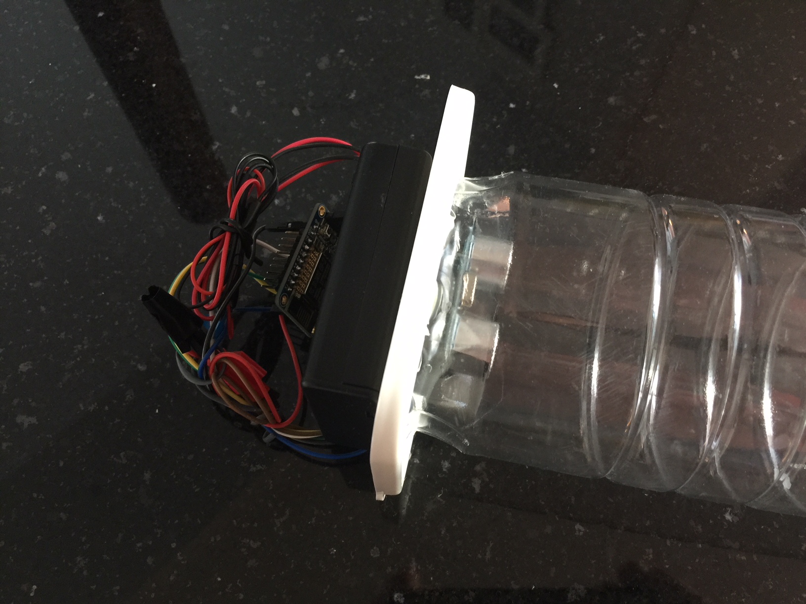
I’ve been having a few issues with the water level in the ponds in the Garden, It’s a pretty complex setup with 3 ponds interconnected with streams. But I’ve been losing water through evaporation and occasionally from the streams themselves. So I thought I’d set myself a little challenge to build a wireless device that kept an eye on the levels to make sure the pump didn’t run dry from lack of water. I had enough little arduino bits lying around to create something so here’s the results.
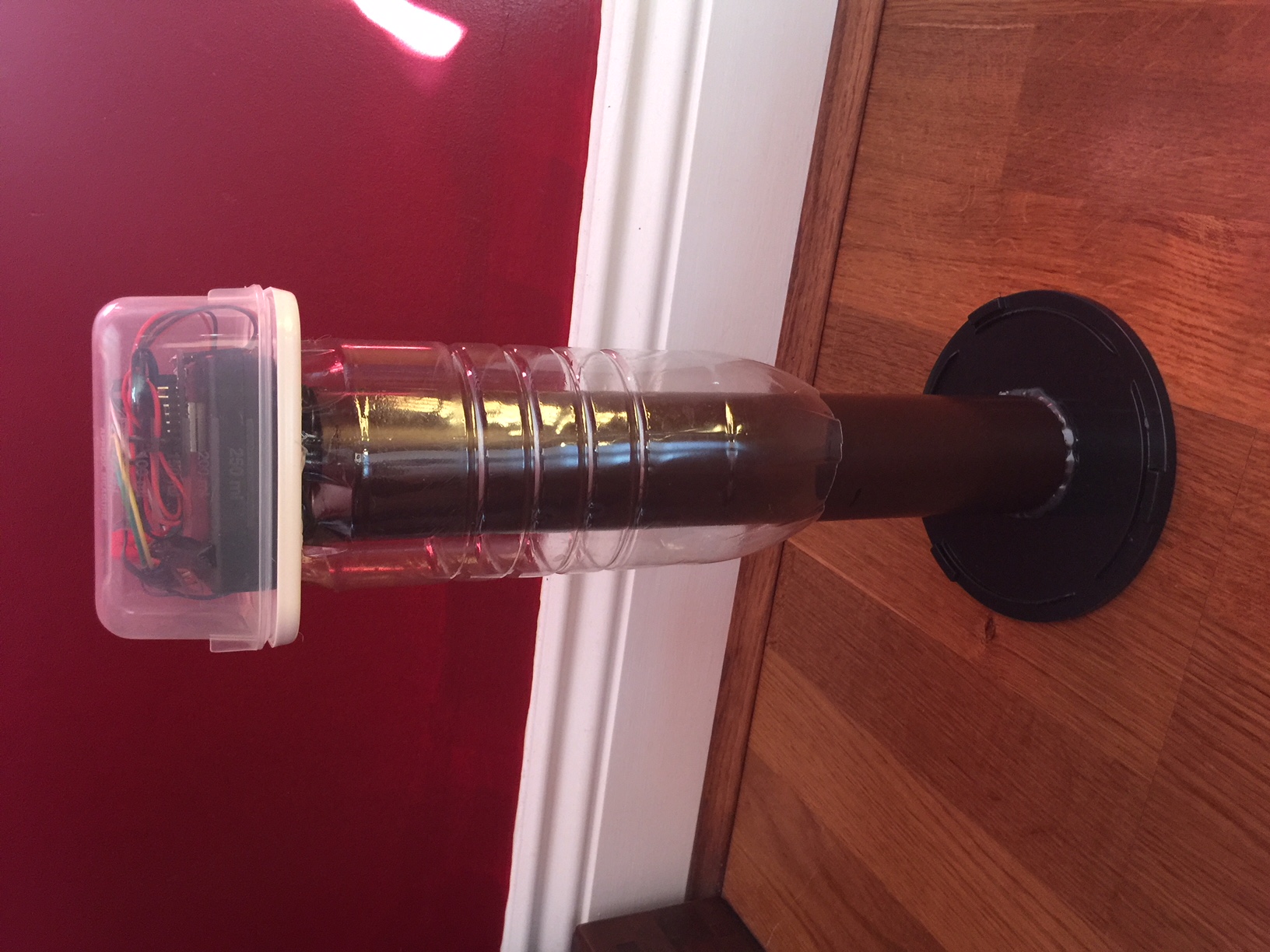
It uses a proximity sensor set above the water to measure the level and I also added a temperature sensor to see what the weather was doing. I connected it all up to a small ESP8266 arduino so I could send the data over Wifi in real time. I then set up a Node JS server on heroku to receive the data which I’m sending data to every 10 minutes. This data is then stored in a simple mongo database. I built a front end monitoring website to keep on eye on everything and it seemed like a good idea to also have a low level warning system added. If the water gets to a low level, I used a free SMS service connected to the Node server to send me an text. Handy if om on holiday and need to get a neighbour to pop round to top it up. The whole device is mounted in a couple of tubes and water tight containers to keep everything dry. Seems to be working ok, just not sure how long the batteries will last, so may have to get clever and add a solar panel. The website to view that feed is here.
http://waterlevel001.herokuapp.com/

And here’s a few pictures of the work as it progressed.
Water Level Meter

Water Level Meter

Water Level Meter

AR Brochure using Vuforia

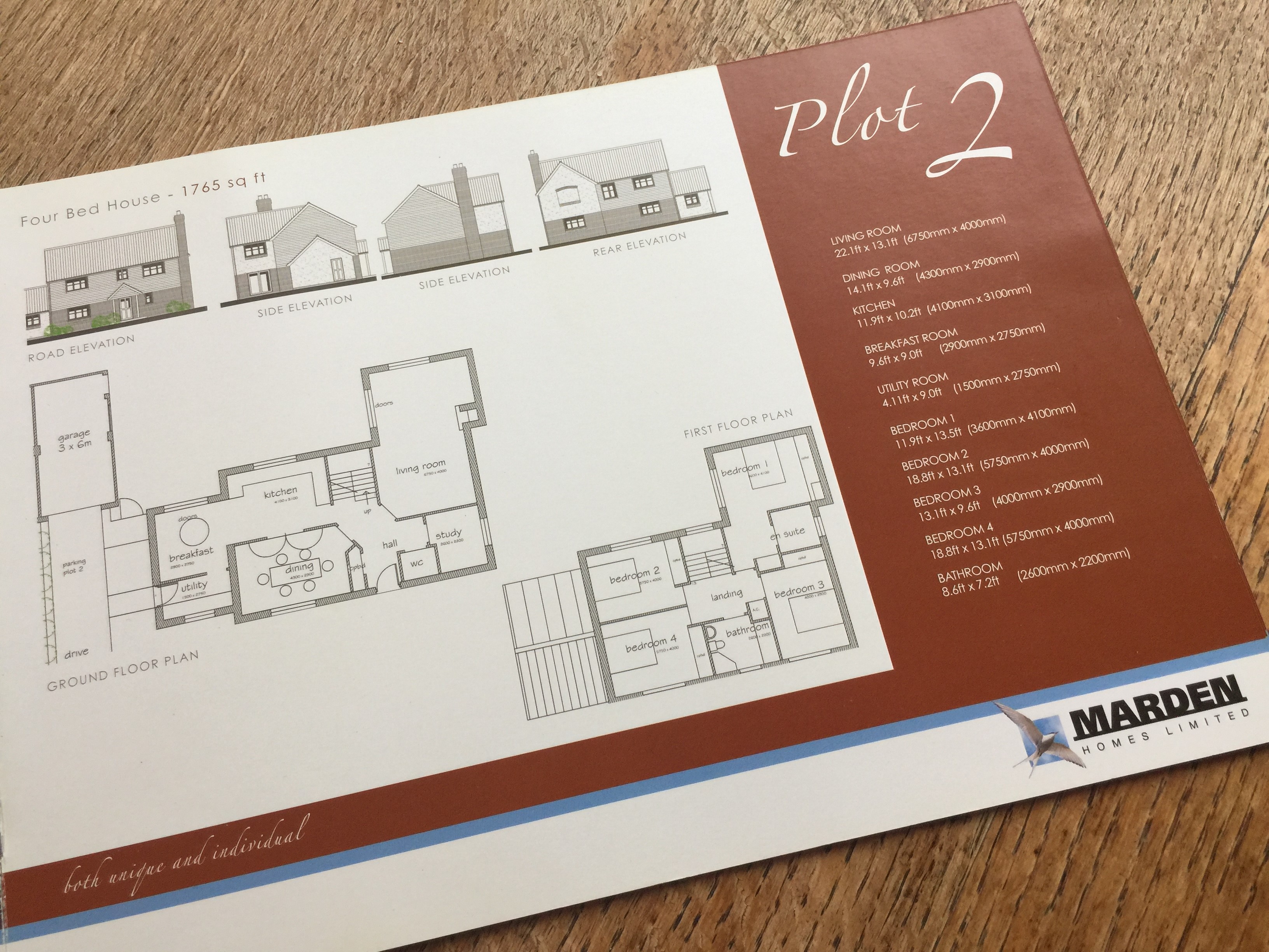
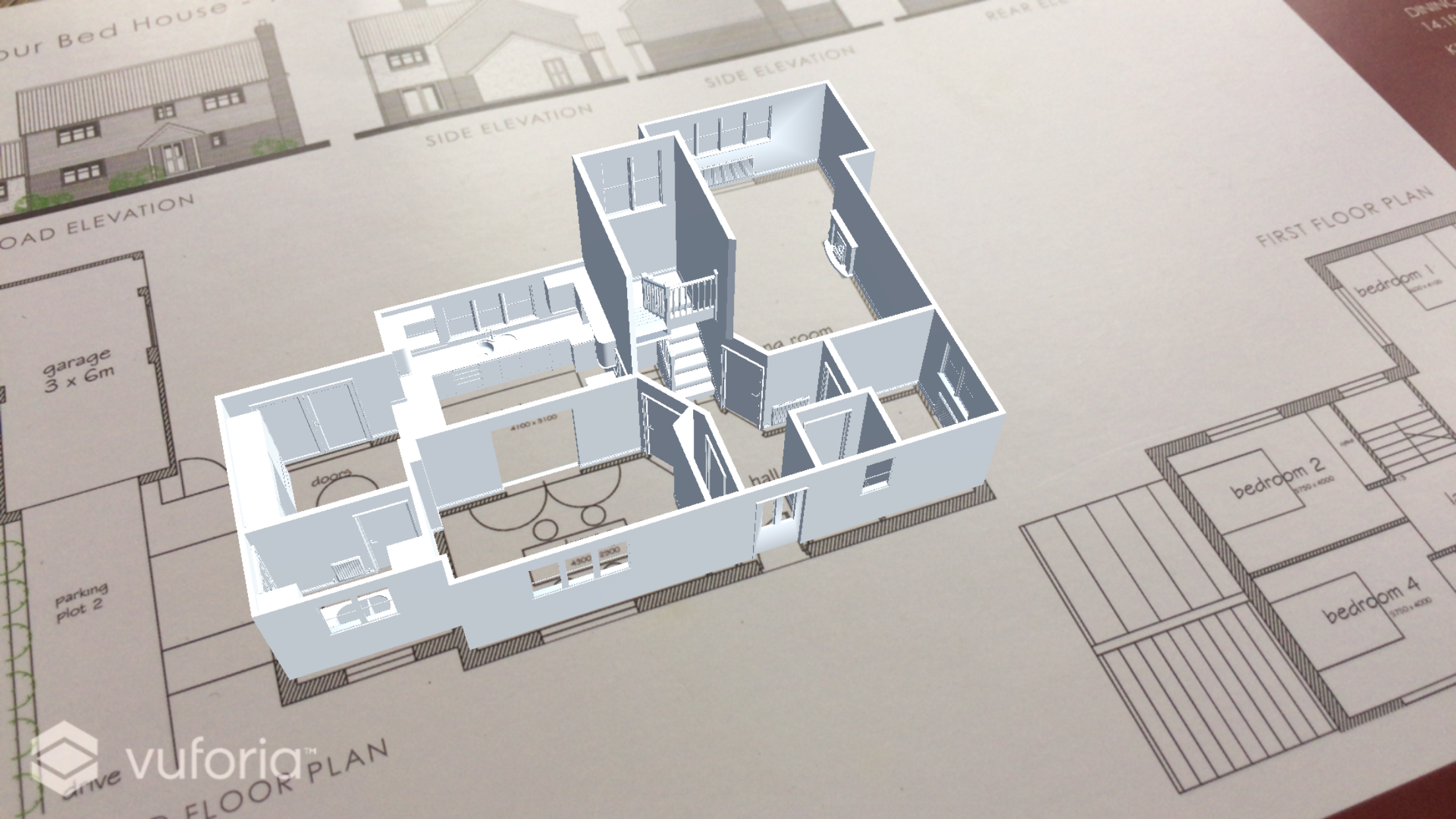
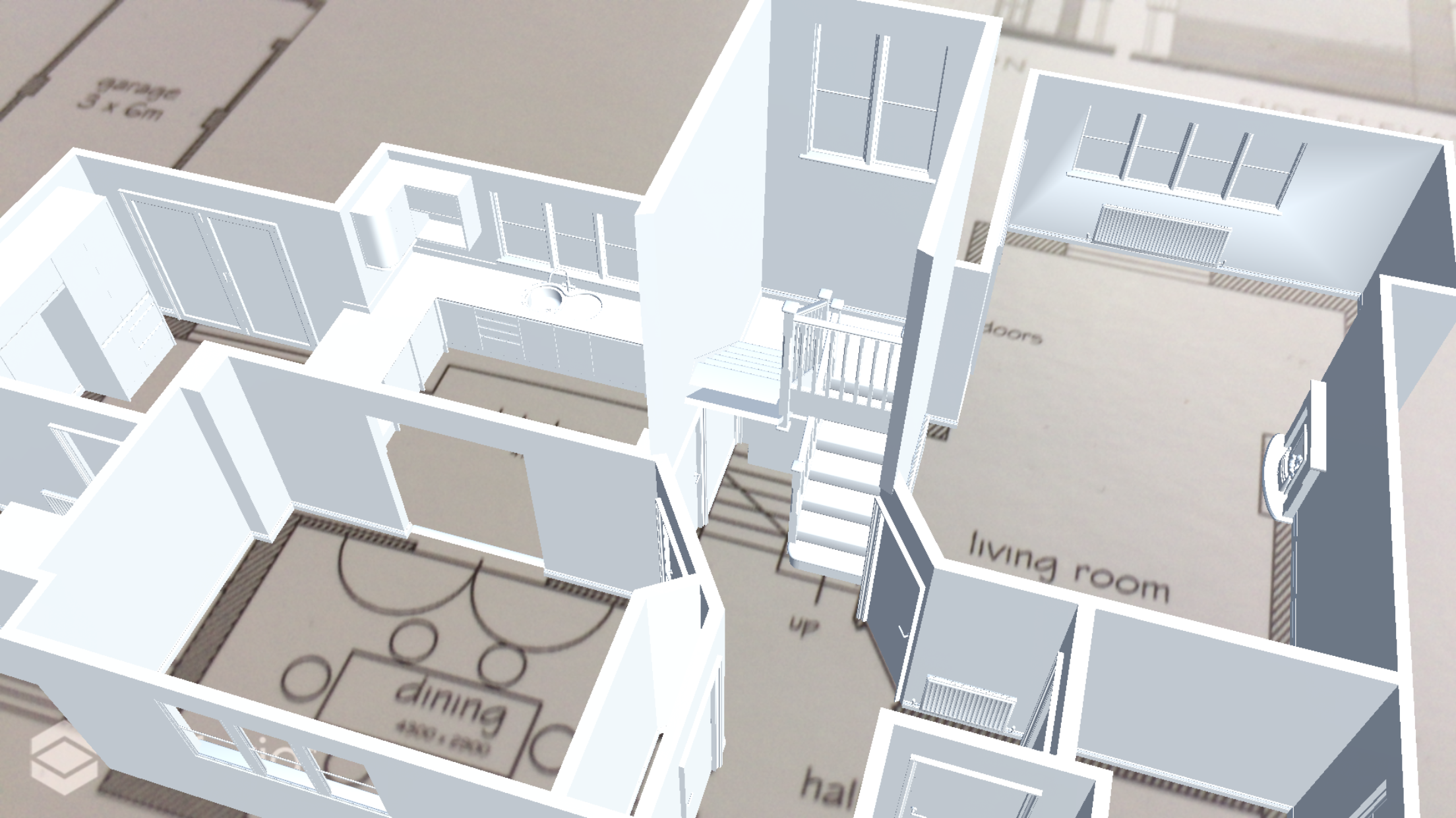
I’ve been looking into the latest Vuforia release included with the last update to Unity. I tried experimenting with the brochure that was used as promotional material when we first moved into our house. By using the brochure page as a target image for Vuforia, I was able to directly overlay a model that I had previously created for a Virtual reality demo directly onto the page. Below are some images of the brochure which show the original brochure and also some images screen captured from the phone APP. At the very bottom is a video captured directly from the phone screen.


Video walkthrough of completed APP

Virtual Reality Customisable room

I’ve just finished a prototype build in Unity to demo a completely customisable 3D room. The room is designed to let the user walk around using a google cardboard and ultimately view video content on either the large cinema screen, or in a completely immersive 360 surrounds environment. The room itself can be customised via a web interface to change all aspects of the environment. From pictures on the walls, videos promos on the TV screens, banner ads, logos and product information on the plinths. The project is part of a new app being developed by Daniel Corazzi and his team. It will form part of the larger offering from the VAR-PORT app currently available on the app store. A demo of the room can be seen here.

Arduino Real World Color Picker to RGB

Whilst creating a few things in VR it would of been nice to get the exact color of the object to use as the Diffuse/Albedo color to use in the shader. I had a look around and theirs a few tools out there to do it like the Nix Color sensor but they were just way to pricy. So had a look into color sensors and Sunfounder make this one “color sensor” for on $12. So thought I’d have a go at making my own with an arduino. Took a couple of hours to cobble it together with a display. But works pretty well, giving a constant reading of the RGB on the left and the average over a couple of seconds on the right. Might make a little enclosure for the sensor to stop the light leaking in but doing the job pretty well for now.

VR Walk through of Show home

Just finished my first complete VR walk through of a show home. The home is actually mine as I had all the plans from the original sale of the house. I built everything down to the last plug socket myself in 3D Studio Max, then imported into Unreal Engine and textured. Finally I added a few interactions to doors cupboards to bring it to life.

Google daydream

VR experiments continuing I’ve finished building another small prototype to test out the functionality of the google daydream controllers in Unreal. Little hard to test in the actual Unreal engine player but you can hook up an old android phone and use that as if it a daydream controller. Also experimented with gaze interaction and adding in some custom loading animations as sprites. To help navigate around a scene if you didn’t have the controllers.

HTC Vive interactions

Been experimenting with how to use the HTC vive controllers and interact with the environment. Finished building a small demo to test out the point and shoot capabilities of interacting with objects. As well as building blueprints that can be re-used and easily edited to do different interactions. Like getting 1 blueprint in unreal to be able to have different meshes assigned to it and animate multiple ways. So one blue print can be used to build a door or window and animate open different ways by simple drop down menus.

Simple walkthrough example shown here